
What are the differences between right-angle, submerged, and straight-through pulse valves? How to select based on requirements?
As the key actuating components in pulse-jet cleaning systems, the electromagnetic pulse valve serves as the compressed air “switch” for pulse-jet baghouse dust collectors. Its performance directly impacts the collector's processing capacity and dust capture efficiency. To assist industry users in accurately understanding the technical differences among the three mainstream pulse valve types—right-angle, submerged, and straight-through—and scientifically formulating selection plans, this article systematically outlines the structure, principles, and applicable scenarios of these valves based on industry technical specifications and product characteristics. It provides reference for dust removal engineering design and equipment operation and maintenance.
I. Core Definitions and Structural Features of the Three Pulse Valve Types
Right-Angle Electromagnetic Pulse Valve
Its characteristic is that the air inlet and outlet pipes of the right-angle valve are at a 90° angle. The valve body and bonnet are die-cast using aluminum alloy material. After surface treatment, they exhibit excellent corrosion resistance. The diaphragm and sealing gasket are produced using a vulcanized composite process. The raw materials for the electromagnetic pilot head consist of high-efficiency magnetic materials and stainless steel magnetic shielding materials.Critical components like springs and fasteners are made of stainless steel. Connection method: The air distributor (air tank) pipe and the dust collector's blowpipe are inserted into the valve's inlet and outlet respectively, sealed by compression nuts at both ends.
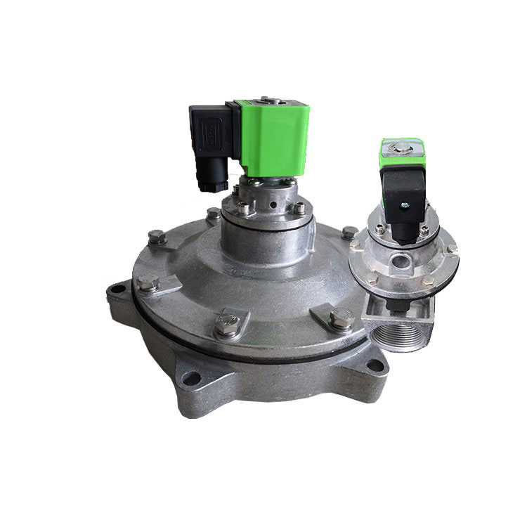
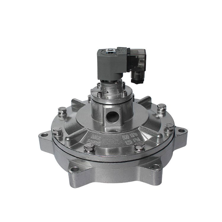
Submerged Electromagnetic Pulse Valve
Consisting of an electromagnetic pilot head, diaphragm assembly (diaphragm, pressure spring, seal), and valve body. Installed submerged within the air reservoir, it connects to the reservoir via a flange. The outlet port is centrally located within the valve body inside the reservoir, extending through components like a wall-penetrating device to enter the blow chamber for operation. This valve type features optimized flow channel design that effectively reduces gas flow resistance, ensuring stable operation even under low-pressure conditions. This design lowers energy consumption and extends diaphragm lifespan.
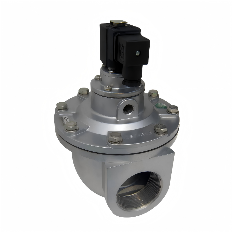
Straight-through Electromagnetic Pulse Valve
The centerlines of the air inlet and outlet are aligned in a straight line without angular deviation, with the gas flow direction clearly marked on the valve body surface. Installation involves connecting one end to the air pipe extending from the air tank and the other end to the air pipe of the blow chamber. Its simple structure facilitates installation, making it a common component in air tank pulse dust collectors.
II. Comparative Analysis of Common and Distinctive Working Principles
Working Principle of Right-Angle Pulse Valves
A diaphragm within the valve divides it into front and rear air chambers. When compressed air is supplied, it enters the rear chamber via a throttle port. The pressure in the rear chamber forces the diaphragm to seal the outlet port, placing the valve in the “closed” state.
An electrical signal from the pulse jet control instrument moves the electromagnetic pulse valve's armature, opening the rear chamber's vent hole. The rear chamber rapidly depressurizes, causing the diaphragm to retract. Compressed air then jets through the valve outlet, placing the pulse valve in the “open” state. The instantaneous release of compressed air creates a jet stream.
When the electrical signal from the pulse controller ceases, the valve armature resets. The rear chamber vent closes, and pressure in the rear chamber rises, forcing the diaphragm back against the valve outlet. The pulse valve returns to the “closed” state.
Working Principle of Submerged Pulse Valve
The pulse valve is divided into front and rear chambers. When compressed air is supplied, it enters the rear chamber through a throttle orifice. The pressure in the rear chamber forces the diaphragm to seal the valve outlet, keeping the pulse valve in the “closed” state.
When an electrical signal from the pulse controller moves the valve armature, the rear chamber vent opens. Rapid pressure loss in the rear chamber causes the diaphragm to move, allowing compressed air to discharge through the valve outlet. The pulse valve enters the “open” state, momentarily releasing a burst of compressed air.
When the electrical signal from the pulse controller ceases, the valve armature resets, the rear chamber vent closes, and pressure in the rear chamber rises, forcing the diaphragm to seal the valve outlet. The pulse valve returns to the “closed” state.
Working Principle of the Straight-Through Pulse Valve
1. Power-Off Closure: Compressed air enters the rear chamber through the throttle hole. Rear chamber pressure > front chamber pressure, pushing the diaphragm to seal the main valve outlet, closing the valve.
2. Power-On Opening: The pulse controller sends a signal, electromagnetic force lifts the armature, opening the vent hole. The rear chamber rapidly depressurizes, creating a pressure differential between the front and rear chambers. The diaphragm moves backward, opening the main valve port, and compressed air is blown out.
3. Power-off Reset: When the electrical signal ceases, the armature spring returns, closing the vent hole. Pressure in the rear chamber is restored through the throttle hole, causing the diaphragm to reset and close the main valve port, returning to the initial state.
III. Key Technical Parameters and Selection Criteria
Core Technical Parameter Standardization: Domestic right-angle and straight-through pulse valves operate within a pressure range of 0.4-0.6MPa. Imported counterparts uniformly operate at 0.4-0.6MPa regardless of type. Both categories exhibit no fundamental differences in pressure tolerance or application pressure ratings.
Three Core Principles for Scientific Selection
1.Operating Pressure Compatibility Principle: For low-pressure scenarios (requiring reduced air source pressure), prioritize submerged electromagnetic pulse valves. For standard pressure conditions (0.4-0.6MPa), flexibly select right-angle or straight-through types based on installation constraints.
2.Installation Space Matching Principle: When the air tank and blowpipe are vertically aligned, use right-angle electromagnetic pulse valves. For linear layouts, use straight-through electromagnetic pulse valves. When internal installation inside the air tank is required, submerged electromagnetic pulse valves are preferred.
3. Equipment Type Correspondence Principle: Air-box pulse dust collectors should primarily use straight-through electromagnetic pulse valves. Pulse baghouse dust collectors can select right-angle electromagnetic pulse valves based on installation angle. For large dust collection systems operating under low-pressure conditions, submerged electromagnetic pulse valves are recommended.
IV. Industry Application Context and Outlook
Electromagnetic pulse valve is extensively used in dust collection applications, and its performance stability directly impacts environmental treatment efficiency and industrial production continuity. As environmental standards continue to improve, the demands for energy-efficient and long-life pulse valves continue to increase. This release of technical comparisons and selection guidelines for three mainstream pulse valve types aims to help industry users avoid selection pitfalls, enhance dust collection system efficiency, and reduce operational costs. In the future, technological advancements will focus on more precise pressure control, extended service life, and broader adaptability to diverse operating conditions, providing core component support for industrial green transformation.
Send Inquiry


X
We use cookies to offer you a better browsing experience, analyze site traffic and personalize content. By using this site, you agree to our use of cookies.
Privacy Policy