
Products


Optipow 135 Piston Pulse Valve
Optipow135 piston pulse valve: diaphragm-free design, long service life, compact installation, ideal for industrial dust cleaning and filtration systems.
Model:Optipow135
Send Inquiry
Product Description
Product Description:
The Optipow135 piston pulse valve is a new-generation embedded electromagnetic pulse piston valve developed based on the diaphragm-type electromagnetic pulse valve and piston mechanism. It makes pulse jets work much better, it doesn't take up much space and it makes it easier to design the jet system.
The Optipow135's working chamber is different from traditional diaphragm valves because it doesn't have any vulnerable parts like rubber diaphragms and pressure springs. Instead, it uses a piston made of high-strength materials, which makes the electromagnetic pulse piston valve last much longer.
Comparison of Installation Spacing Between the Optipow135 and Standard Diaphragm-Type Pulse Valves of the Same Specification
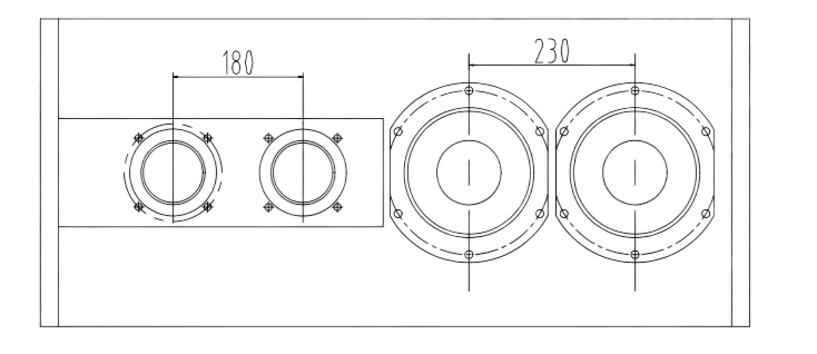
Figure 1
Note: The installation spacing for both the Optipow105 and Optipow135 is 180 mm (minimum 160 mm).
Product Parameter:
|
Specification Item |
Details |
|
Model NO. |
OPTIPOW 135 |
|
Valve Structure |
Piston Structure |
|
Power Supply |
Solenoid Valve |
|
Usage |
Dust Cleaning |
|
Standard |
DIN |
|
Application |
Industrial Usage |
|
Used For |
Dust Filter |
|
Trademark |
OPTIPOW |
|
Specification |
4" |
|
Design Static Pressure |
15 bar (1500 kPa) |
|
Design Temperature |
100 °C |
|
Operating Pressure |
< 6 bar |
|
Operating Pressure Variation |
3 bar unlimited nos |
|
Operation Temperature |
50 °C |
Installation Instructions
① Fill the threads with PTFE tape or thread sealant for tightening and sealing. The mating surface of the air manifold must be flat. Ensure the mating surface is flat, straight and smooth to guarantee its sealing performance.
② Install a filter and pressure regulator on the inlet pipe of the air manifold, and a drain valve at the bottom of the air manifold to ensure no accumulated water in the manifold and that the compressed air is dry and clean.
③ The end face for air tank installation must be machined in accordance with the air tank machining schematic. Strictly meet the cleanliness requirements for the air tank installation surface.
④ Before valve installation, ensure the inside and outside of the air tank and blowpipe are clean and free of debris particles.
⑤ Refer to Figure 2 for the machining schematic of the air manifold connection.
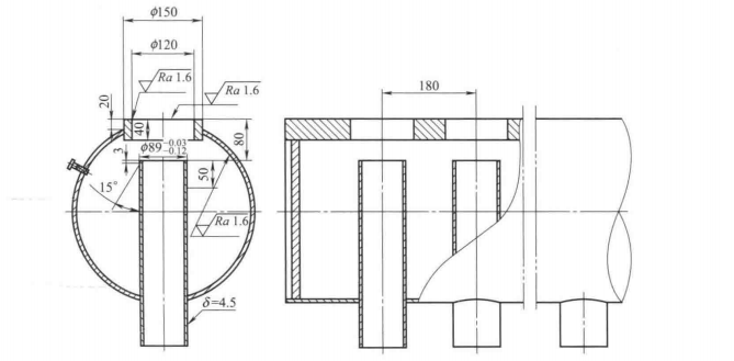
Figure 2
Hot Tags: pulse valve, solenoid valve, plunger valve, piston valve
Related Categories
Piston Pulse Valve
ASCO Pulse Valve
DMF Pulse Valve
Goyen Pulse Valve
Piston Pulse Valve Spare Parts
Pulse Valve Spare Parts
Send Inquiry
Please feel free to fill your inquiry in the form below. We will reply you in 24 hours.


X
We use cookies to offer you a better browsing experience, analyze site traffic and personalize content. By using this site, you agree to our use of cookies.
Privacy Policy